
This seems to be an engineering sample CPU. Since these are pre-production, that could mean it’s basically a fully functional CPU. It could also have serious issues.
- 0 Posts
- 14 Comments
Joined 2 years ago
Cake day: July 2nd, 2023
You are not logged in. If you use a Fediverse account that is able to follow users, you can follow this user.
You can use most of the connectors you would use for bigger wires. Wago lever nuts are rated for conductors as small as 0.14 mm².
If you want something to fit a din rail, standard terminal blocks (something like this) should also work.


 5·4 months ago
From the IRF1404Z data sheet:
Calculated continuous current based on maximum allowable junction temperature. Bond wire current limit is 120A. Note that current limitations arising from heating of the device leads may occur with some lead mounting arrangements.
You need to design the PCB so that the heat from the legs can be properly dissipated, or they won’t live up to the rated current.
Also, traces on a PCB are much thinner than those legs. A trace with the same cross-sectional area would be impractically wide.
 183·8 months ago
Unpopular opinion: The license makes sense and should have been enforced from the start.
The Benchy is a benchmarking tool, not just visually but there are also various features you can measure and check against the dimensions on the website. But that doesn’t work if the model you’re printing has been modified.
If it looks like a beachy, it should have been printed from the original model, so it’s always comparable. Preventing derivatives means you can be sure of that, even if it came on the included SD card with your printer. Otherwise, manufacturers could include a modified model that makes their printers look better than they are.
If you can wait a couple weeks, AliExpress is going to be the cheapest.
eBay may be a bit more expensive, but it’s often my go-to because you can find everything and usually there are options with short shipping times.
For not too obscure parts, I would look at Reichelt, their prices are surprisingly low (especially if you bundle your orders to save on shipping costs).
That’s probably not a bad idea, although I doubt it will make much of a difference. But since you’re redesigning the whole thing, might as well do it.
It looks like you would want an even airflow through the whole PSU. The main heat-generating components are using the sides of the housing as a heat sink. I’m guessing the fan is mostly so the air inside the housing doesn’t get too warm, not to cool individual components.
Where is the original air exhaust? If it’s near the bottom of the picture, that would confirm my theory. In that case, I would keep the fan placement as close to original as possible (i.e. the blue square).
You can use a boost converter to boost the 5V of an USB port to the 19V your notebook needs.
Assuming 5A output from a powerbank (which is probably about the max you will get without USB PD), you could theoretically get 0.55A at 19V. With the unavoidable inefficiencies, you will get less.
So, maybe enough to very slowly charge your notebook while it’s off. But when it’s turned on, the battery charge will still drop.
This seems to be a bug in the slicer. I’m seeing the same issue in OrcaSlicer if the skirt height is set to more than one layer (even if the skirt is disabled). This makes sense if a skirt is used (can’t print a continuous spiral if you have to switch between printing the object and the skirt), but not if it’s disabled.
What slicer are you using? If it’s a PrusaSlicer fork, this is likely the same bug.
From a cursory read of the datasheet, using the “dead time control” pin seems to be the way to go. Basically, this pin is used to set the voltage, while the error amplifier inputs (that’s the closest function to “over current protection” this chip has) are used to adjust the output according to the load. For your application, you probably don’t need to use them at all.
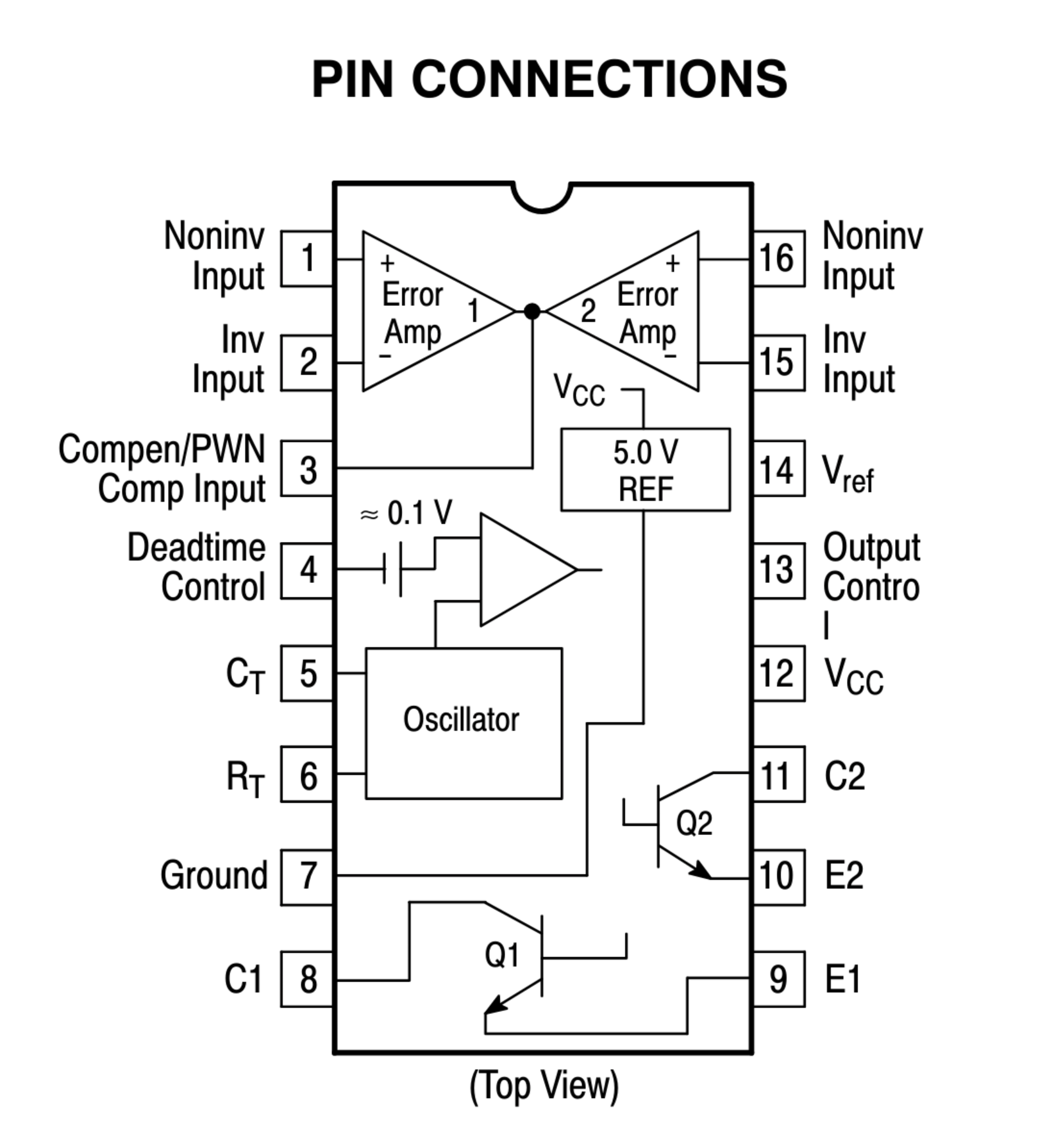
My instinct would be to disable the error amplifiers by connecting pins 1,2,15 and 16 to GND. You can then connect the wiper pin of the potentiometer to the deadtime control input, with the other pins of the potentiometer connected to GND and 3.3 V.
I haven’t worked with this chip before, so take this with a grain of salt. You should probably use a simulation tool to check the circuit before you start destroying chips.
My router is called Jupiter, everything connected to it is named after a moon. Callisto, Ganymede, Thelxinoe, Kallichore are what I’m currently using.
Reminds me of this: Falsehoods Programmers Believe About Names

 19·2 years ago
It’s called HDR (High Dynamic Range) photography. Your phone is taking three pictures: one at a medium exposure, one at a bit higher exposure and one at a bit lower exposure.
The higher exposed picture will have a blown-out sky, but more detail in the darker area, while the lower-exposed one will have a correctly exposed sky with the darker areas underexposed.
These pictures are then combined by taking the correctly exposed areas of each picture, i.e. the sky from the low-exposure picture and the shadows from the high-exposure one, giving you a single picture without over- or underexposed areas.
I don’t know about OpenCamera, but you should be able to select the size of the exposure bracket, meaning how much higher or lower the different pictures are exposed.
He proposes the cloud be owned by communities, so in a way by everyone. That’s not the same everything being owned by private companies.